Friday, January 31, 2020
Sunday, January 19, 2020
HSRP
Router redundancy (Hot Spare Router Protocol below)
1. Simple Layer 3 Redundancy: (R1 perspective)

Static route to SP1:
ip route 0.0.0.0 0.0.0.0 203.0.113.1
If link to SP1 is down, backup defalult static route via R2:
ip route 0.0.0.0 0.0.0.0 10.10.20.2 5
(5) set Administrative Distance to 5 so as not to load balance traffic
If link to CD1 is down, backup route to inside network via R2:
ip route 10.10.10.0 (/24) 10.10.10.20.2
No need to set AD, as this static route's AD by default is 1, and the existing Connected Link has a default AD of 0 so the Connected route will be preferred automatically.
Redundancy for the PCs
Setting up half the PCs to default-gateway of R1, and the others to R2 is not preferable, much manual work if a router is not reachable..therefore-
2. FHRP - First Hop Redundancy Protocols
- These use Virtual IPs and MAC addresses to allow for automated gateway failover.
- The host uses the VIP as their gateway address, and if a physical gateway fails, another gateway takes over.
- HSRP is a Cisco proprietary FHRP deployed in active/standby pair.
- VRRP (Virtual Router Redundancy Protocol) is an open standard, deployed in active/standby pair. Very similar to HSRP.
- GLBP (Gateway Load Balancing Protocol) is Cisco proprietary and supports active/active load balancing across multiple routers
- HSRP:

- Routers have unique physical IP and MAC addresses
- Routers then also have the HSRP VIP and MAC address too
- When they come online, one is elected as the HSRP active router (holds the VIP and MAC address) and the other in standby
- The active route then responds to ARP requests and all traffic for the VIP goes through the active router
- The routers send hello messages to each over their HSRP interface. (R1 sends hello to R2: the source would be 10.10.10.2 and the destination is 10.10.10.3)
- If the standby router stops receiving hellos it will transition to the active router and take ownership of the VIP and MAC and respond to ARP requests
- R1(config)# inter gi0/1
- R1(config-if)# ip address 10.10.10.2 255.255.255.0
- R1(config-if)# no shut
- R1(config-if)# standby 1 ip 10.10.10.1
- R2(config)# inter gi0/1
- R2(config-if)# ip address 10.10.10.3 255.255.255.0
- R2(config-if)# no shut
- R2(config-if)# standby 1 ip 10.10.10.1
- Verification: show standby
- note: the command to show PC ARP table C:\arp -a
- HSRP Priority and Pre-emption
- If Priority is enable, you can define which router will be active if both routers are booted at the same time
- The default is 100 if not defined, but the higher priority number will win if set
- In the event of a Priority tie, the hightest IP address wins
- If Pre-emption is enabled also, when a higher priority router comes back online after a failure it will transition back to active
- If pre-emption is not enabled (default), the lower priority router will remain active when the failed router comes back online (this can be more stable if the higher priority router is flapping)
- R1(config-if)# standby 1 priority 110 (add to above R1 commands)
- R1(config-if)# standby 1 preempt
- R2(config-if)# standby 1 priority 90
- HSRP version 2 introduces some improvements, however, version 1 is the default. NOTE: both routers must have some version.
- R1/R2(config-if)# standby version 2
Wednesday, January 15, 2020
DHCP
Dynamic Host Configuration Protocol

Option 1: Cisco DHCP Server Configuration
Option 2: External DHCP Server Configuration
Option 3: Cisco Router as DHCP Client
- DHCP is a client/server protocol that automatically provides a host with an IP address, subnet mask, and default gateway.
- Can assign additional IP configuration values by means of DHCP options like the TFTP address for phones to find the phone system
- DHCP relay agent can forward initial DHCP messages throughout the campus so a server is not needed on every network or subnet
- Candidates are PCs and laptops, not servers or network infrastructure.
- UDP port number 67 for the DHCP server, and the UDP port number 68 for the client.

Option 1: Cisco DHCP Server Configuration
- R1(config)#ip dhcp exclude-address 10.10.10.1 10.10.10.10 (enter this first so these addresses are not assigned by turning dhcp on)
- R1(config)#ip dhcp pool 10.10.10.0_Clients (any name can be assigned)
- R1(dhcp-config)# network 10.10.10.0 255.255.255.0 (network to be handed out)
- R1(dhcp-config)# default-router 10.10.10.1
- R1(dhcp-config)# dns-server 10.10.20.10
- Verification
- Show ip dhcp pool
- Show ip dhcp binding (shows assigned IP addess to MAC address)
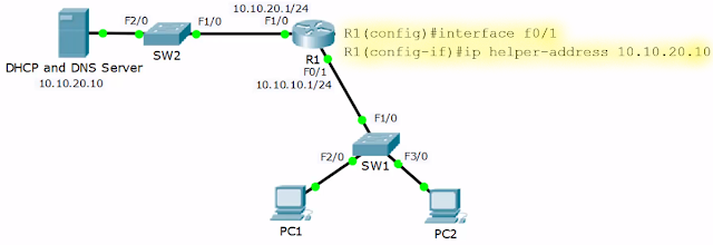
Option 2: External DHCP Server Configuration
- If the DHCP server is on a different subnet, the Router interface facing the clients need not block the DHCP request broadcast traffic, but to help it through the network
- R1(config)#interface fa0/1
- R1(config-if)# ip helper-address 10.10.20.10

Option 3: Cisco Router as DHCP Client
- Example: if router interface connects to an ISP and there is on need for a static internet address
- R1(config)# interface gi0/0
- R1(config-if)# ip address dhcp
- R1(config-if)# no shutdown
- Verification
- show dhcp lease
Monday, January 13, 2020
Inter-VLAN Routing
There are three options for routing between VLANs:
1. Having a separate, physical router interface for each VLAN....ugh!
2. Router on a Stick: all VLAN's traverse and share one link to the router, however, there is more contention for bandwidth than using separate interfaces. This is accomplished by using Virtual Sub-Interfaces on the router.

1. Having a separate, physical router interface for each VLAN....ugh!
- Each router interface has the default gateway IP address for the subnet, and the adjacent switch port is set to mode access.
2. Router on a Stick: all VLAN's traverse and share one link to the router, however, there is more contention for bandwidth than using separate interfaces. This is accomplished by using Virtual Sub-Interfaces on the router.

- R1(config)# interface fa0/1
- R1(config-if)# no ip address
- R1(config-if)# no shut
- R1(config)#interface fa0/1.10 (creates the sub-interface)
- R1(config-if)# encapsulation dot1q 10 ('10' is VLAN number)
- R1(config-if)# ip address 10.10.10.1 255.255.255.0
- R1(config)#interface fa0/1.20
- R1(config-if)# encapsulation dot1q 20
- R1(config-if)# ip address 10.10.20.1 255.255.255.0
- R1(config)# ip router 0.0.0.0 0.0.0.0 203.0.113.2
- SW1(config)# interface fa0/1
- SW1(config-if)# switchport mode trunk
3. Layer 3 Switch (probably not on the CCNA test)

- Traffic being routed within the campus is routed across the backplane of the switch and not through cabling to an external router.
- You must enable routing on this special layer 3 switch, and you will probably have a router for WAN connectivity and services.
- SVI - Switched Virtual Interfaces are used for routing.

- First, configure routing in the switch and the SVI
- SW1(config)#ip routing
- SW1(config)#interface vlan 10 ( SVI )
- SW1(config-if)# ip address 10.10.10.1 255.255.255.0
- SW1(config)#interface vlan 20 ( SVI )
- SW1(config-if)# ip address 10.10.20.1 255.255.255.0
- Second, config WAN routing on the switch
- SW1(config)#interface fa0/1 ↓ changing to a layer 3 interface ↓
- SW1(config-if)# no switchport
- SW1(config-if)# ip address 10.10.100.1 255.255.255.0
- SW1(config)# ip route 0.0.0.0 0.0.0.0 10.10.100.2 (default gateway)
- Then matching configuration on the router
- R1(config)# interface fa0/1
- R1(config-if)# ip address 10.10.100.2 255.255.255.0
- R1(config)# interface fa0/2
- R1(config-if)# ip address 203.0.113.1 255.255.255.0
- R1(config)ip route 0.0.0.0 0.0.0.0 203.0.113.2 (default gateway)
- R1(config)ip route 10.10.0.0 255.255.0.0 10.10.100.1 (router for internal LAN traffic - this is a summary router for both the .10 and .20 network)
Tuesday, January 7, 2020
VLAN

Campus Topology Design
- Access Layer: PC, IP Phones, and Printers are at this layer that is designed for high port count and affordable cost. Client access security measures are enabled at this Access Layer.
- Distribution Layer: access layer switches uplink to 'typically' redundant distribution switches, thus providing scalability. No host at this layer and most software policy like Qos is enabled here.
- Core Layer: distribution switches uplink here to typically redundant core switches, it is designed for speed and resiliency so rarely are software policies enable here --> this would slow the core.

- Collapsed Design for smaller campuses (LETU)
- Access Layer is the same as above.
- Distribution/Core Layer

VLAN- Virtual Local Area Network
- VLANs increase performance and security within a network
- They segment the LAN into separate broadcast domains at Layer 2
- typically a one-to-one relationship between an IP subnet and a VLAN
- Types of VLANs:
- Default VLAN- initial startup VLAN - Cisco default is VLAN 1
- Data VLAN - referred to as the user VLAN
- Management VLAN - for admins to manage the switch
- Voice VLAN - for voice traffic
- Native VLAN - is assigned to a 802.1Q trunk for untagged traffic
- Access Ports
- Access ports are configured on switch interfaces for end-hosts and end-host are not aware of the VLAN
- Access ports are configured with one specific VLAN
- VLAN1 by default, which is also the Native VLAN
- SW1(config)#vlan 10
- SW1(config-vlan)#name Engineering
- SW1(config)# interface Fa0/1
- SW1(config-if)#switchport mode access (dynamic by default)
- SW1(config-if)#switchport access vlan 10
- SW1(config-if)#interface range FastEthernet 0/3 -12
- SW1(config-if)#switchport mode access
- SW1(config-if)#switchport access vlan 10
- Verification
- #show vlan brief (brief stats of all ports)
- #show interface Fa0/1 switchport (stats individual port)
- Trunk Ports:
- Links that carry traffic for multiple VLANs between switches
- Dot1Q is the current trunking protocol - ISL(Inter-Switch Link) is cisco proprietary trunking protocol that is obsolete
- Dot1Q - when traffic traversed switch to switch it tags the layer 2 header with the Dot1Q info (correct VLAN). The receiving switch only forwards traffic to ports in the same VLAN, and it removes the Dot1Q tag from the Ethernet frame.
- Note: with a server running multiple virtual machines (like VMware or HyperV), that port would also be a truck as it may need to be in multiple LANs.
- SW1(config)#interface fa0/24
- SW1(config-if)#description Trunk to SW2 (optional)
- SW1(config-if)#switchport trunk encapsulation dot1q (command for old switches)
- SW1(config-if)#switchport mode trunk
- SW1(config-if)#switchport trunk native vlan 199 (199 unused)
- Native VLAN - this was assigned to any traffic that was not VLAN tagged coming from a trunked port (Hub to Switch: hubs are only layer 1 and not VLAN aware).
- The default Native VLAN is 1, however, there are security issues here so the best practice is to change it to an unused VLAN.
- The Native VLAN must match on both sides of the trunk.
- Verification
- SW1#sho interface fa0/1 switchport
- Limiting Allowed VLANs - you can specifically limit the VLANs that can traverse a trunk for security and performance reasons. This must be set on both sides of the trunk, and if not set, all VLANs will traverse the link.
- SW1(config)#interface fa0/24
- SW1(config-if)#switchport trunk allowed vlan 10,30
- DTP - Dynamic Trunking Protocol
- If connecting two Cisco switches, they can negotiate the trunk connection using DTP, however, this is not recommended.
- Switchport mode dynamic auto: if the neighboring switch port is set to trunk or desirable, the link will automatically form a trunk. However, if both sides are set to auto, a trunk will not form.
- Switchport mode dynamic desirable: will form a trunk if the neighbor switch is set to trunk, desirable, or auto
- Swichport nonegotiate: disables DTP
- VTP - VLAN Trunking Protocol
- allows you to add, edit or delete VLANs on switches configured as VTP Servers, and all other VTP Client switches will synchronize their VLAN databases with it.
- Note: port level VLAN assignments must still be made
- If you have multiple VTP Servers, the one with the highest revision number on the domain will be king
- VTP Server: can add, edit, or delete VLANs
- VTP Client: not able to add, edit, or delete. Looks for highest revisioned VTP Server on domain
- VTP Transparent: does not participate in the Server/Client VTP but will pass the database updates through the switch. It can maintain its own VLAN database. NOTE: if you want tagged traffic to flow through the switch, it must have the VLAN in the database.
- SW1(config)#vtp domain LETU ('LETU' must be on all switches)
- SW1(config)#vtp mode server or
- SW1(config)#vtp mode client or
- SW1(config)#vtp mode transparent
- Verification: SW1#show vtp status
Saturday, January 4, 2020
OSPF
Open Shortest Path First
- Link state protocol; supports large networks; has very fast convergence; messages are sent multicast; is an open standard; uses Dijkstra's Shortest Path First algorithm for best path determination
- A router passes information to its directly connected neighbor, this information is then passed unchanged from one router to another (unlike Distance Vector Routing Protocols)
- OSPF routers use LSA Link State Advertisements to pass routing updates; Packet Types:
- Hello: after OSPF is enabled on an interface, it will send and listen for Hello packets to form adjacencies on the link
- DBD - DataBase Description: adjacent routers will tell each other the networks they know about with the DBD packet
- LSR - Link State Request: if a router is missing information about any of the networks in the received DBD, it will send the neighbor an LSR
- LSA - Link State Advertisements: a routing update, and a replay to the LRS
- LSU - Link State Update: Contains a list of LSA's which should be updated, used during flooding
- LSAck: Receiving routers acknowledge LSA's
Standard Configuration:
R1(config)#router ospf 1
R1(config)#router ospf 1
- Process ID (ospf 1) is only locally significant, as different interfaces can have different Process IDs running unique instances of OSPF
- If different, each interface will have different Link State Databases within the router and will not share information with each other
- However, adjacent routers can have different Process ID and they will share OSPF database information
- The network command uses a wildcard mask format which is the inverse of the subnet mask - subtract each octet by 255 to calculate.
- subnet mast of 255.255.0.0 equals wildcard mask of 0.0.255.255
- and 255.255.255.252 equals wildcard mask of 0.0.0.3
- You must specify the wildcard mask, unlike eigrp
- Network Command means:
- look for interfaces that fall within this IP range then enable OSPF on those interfaces
- Send out and listen for OSPF hello messages and peer with adjacent OSPF routers
- advertise the network and mask which is configured on those interfaces
- R1(config-router)#network 10.0.0.0 0.0.255.255 area 0


Verification Commands:
R1#show run | section ospf
R1#show ip protocols
R1#show ip ospf interface brief
R1#show ip ospf neighbor
R1#show ip ospf database (shows all the links in an area)
R1#show ip route ( (o) is the ospf designation)
Router ID
R1#show run | section ospf
R1#show ip protocols
R1#show ip ospf interface brief
R1#show ip ospf neighbor
R1#show ip ospf database (shows all the links in an area)
R1#show ip route ( (o) is the ospf designation)
Router ID
- OSPF routers identify themselves to each other with an ID that looks like an IPv4 address
- This ID will default itself to the highest loopback IP address and if none configured, to the highest interface address
- Loopback interfaces never go down, therefore, best practice is to have a loopback on your router or manually set the Router ID
- R1(config)#router ospf 1
- R1(config-router)#router-id 2.2.2.2
- if other router interfaces are already up, you must disable/enable ospf for the ID to take effect or reboot router
- A Passive interface will be advertised in OSPF and other routers will be able to get to that network, however, the interface will not form any adjacencies or send out any internal information
- R1(config)#router ospf 1
- R1(config-router)#passive-interface loopback 0
- R1(config-router)#passive-interface gi0/0
- Note: conversely, make all interfaces passive and undo the interfaces needed
- R1(config-router)#passive-interface default
- R1(config-router)#no passive-interface g0/0
Default Route Injection

- R4(config)#ip route 0.0.0.0 0.0.0.0 203.0.113.2
- R4(config)#router ospf 1
- R4(config-router)#default-intformation originate

Notes:
- Speed and Clock Rate- is the rate that the physical interface will transmit; change the Speed or Clock Rate ⇨ it changes the physical transmission speed.
- GigabitE = 1000 mbps
- FastE = 100 mbps
- Serial = 1.544 mbps
- Bandwidth - affects software policy on the router, like influencing EIGRP and OSPF path selection, or how much bandwidth will be guaranteed to a traffic type by Qos.
- Normally, Speed and Bandwidth by default are the same
- The 'Bandwidth' setting on an interface does not affect the physical transmission rate.
Metric Calculation


- The router will learn all the destinations in its area, and the links and their cost; then select the routes based on the lowest cost to a destination.
- Cost is automatically derived from the interface bandwidth
- Cost = Reference Bandwidth / Interface Bandwidth
- Reference Bandwidth default is 100 Mbps
- FE link cost by default is 1 (100/100)
- T1 link cost by default is 64 (100/1.544)
- GE default is 1 (100/1000) (1 is the smallest number)
- Reference Bandwidth modification: affects all interfaces on router
- R1(config)#router ospf 1
- R1(config-router)#auto-cost reference-bandwidth 100000
- FE cost would be 1000 (100000/100)
- GE cost would be 100 (10000/100)
- Set the same reference on all routers
- Manipulating the OSPF Metric in two ways:
- Change the bandwidth on an interface (not recommended)
- R1(config)#interface serial1/0
- R1(config-if)#bandwidth 768
- Manually change the cost by overriding the automatic OSPF cost
- R1(config)#interface fa0/0
- R1(config-if)#ip ospf cost 50
- R1#show ip ospf interface fa0/0 (for verification)
OSPF Areas - only for really large networks
- This supports a hierarchical design that segments large networks into smaller areas. The router maintains full information about its own area, but only summary information about other areas.
- Areas reduce router memory needs
- Areas limit router updates to within the area and reduce CPU resources
- Two-level hierarchy:
- Transit area (backbone or area 0): generally does not contain users
- Regular areas (nonbackbone area): used to connect end-users to the Transit area, by default all traffic goes through the TA

- R1(config-router)#network 10.0.0.0 0.0.255.255 area 0
- The network command looks for interfaces inside this network range and addes that interface to area 0
- For a router to form an adjacency, the neighbor will need to be in the same area
- Area Border Routers (ABR)(R2 below) routers with interfaces in multiple areas
- it separates LSA flooding zones
- it functions regularly as the source for default routes
- it maintains the LSDB for each area that it is connected to
- ideally, the ABR is connected to 2 areas (the backbone and another), with three areas being the upper limit
- it becomes the primary point for area address summarization
- ABRS do not automatically summarise
- If not manually summarized, the routes are flooded everywhere

- #show ip route displays these routes as O IA
- Autonomous System Boundary Routers (ASBR)
- these redistribute into OSPF networks
- they are running OSPF but may also be running other routing protocols that need to be redistributed into the network
- #show ip route displays these routes as O*E1 or O*E2

Subscribe to:
Comments (Atom)
-
 Today, played a little catch with Rowan , the went to a new coffee shop in Shreveport called MOOR Coffee Co (they have a good cappuccino...